Understanding the ATP
The ATP (“Automatic Tool Path”) is certainly the simplest method for nesting in EzyNest. Accessed by pressing the ATP Setup button  on the toolbar, it allows you to import files that have been created by exporting machining ([F8] key) from within CabMaster, position all of each cabinet’s parts on the nesting plate, apply toolpaths, and create labels for each nested part. Also see the page CabMaster to EzyNest using the ATP on our online knowledge base.
The Automatic Toolpath Setup screen has five tabs: Define Layers, Ordering and Nesting, Parts List (or “AMS” if using EnRoute), Select Files and Setup. This HowTo document will detail each of these screens.
Define Layers
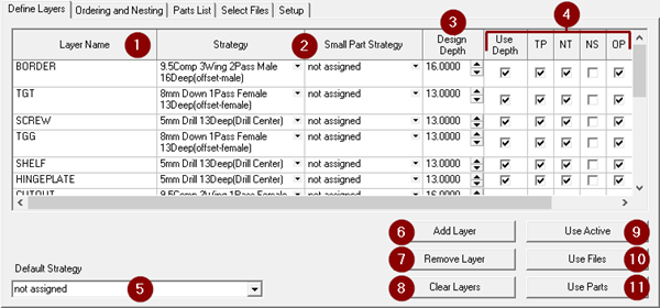
#1: Layer Name
In the Define Layers tab, the Layer Name column contains a list of layers that may correspond to the layers included in the DXF files of the jobs to be processed. These layers are a collection of drill holes, rebates, routes, and other various shapes, that when combined with Strategies, will create the toolpaths that are applied to the parts on the nest.
The Layers can be identified in CabMaster. In any cabinet that has machining applied, on the page Cabinet Machining " View, turn on the checkbox and select the part you wish to view. On any of the toolpaths, right-click and select Edit Machining Props.
The Layer name here is
Hinge_35mm
#2: Strategy / Small Part Strategy
The Strategy and Small Part Strategy columns define which toolpath will be applied to that particular layer. The Small Part Strategy will be used for any parts that have a surface area that is less than the threshold defined in the EzyNest Preferences dialog (menu Setup " Preferences " Initialization).
#3: Design Depth
This refers to the depth for which the selected Strategy was configured.
When Strategy Templates are created, the strategy is created with a specific depth. If a routing offset depth is set to a depth of 16mm, then this is the depth at which toolpaths will be created when this strategy is applied. If this strategy is used to cut out material that is 16mm thick, then this works great. However, if you also want to use this same strategy to cut out material that is 18mm thick, there could be a problem. The
Design Depth
parameter helps solve this issue. In this case, you would set
Design Depth
to 16mm, and click on
Use Depth
to put a tick in the checkbox.
#4: Checkboxes
Use Depth: When the DXF geometry is created by CabMaster, it is typically placed at the depth at which it is intended to cut. Routes that are to be cut at 16mm are placed 16mm below zero in the vertical (Z) axis. If
Design Depth
is specified, and
Use Depth
is ticked, EzyNest uses the vertical position of the route to determine whether to automatically adjust the Strategy depth. In our example, if the route is at -16mm, then no changes are made, but if the route is at -18mm, then the strategy would be modified to have a depth of 18mm. This means that the same strategy could be assigned to layers that will import geometry at different depths.
TP: Toolpath: This provides an option for creating toolpaths for the geometry on each layer. Most of the time this parameter should be ticked. There may be cases, however, where information on a particular layer should not get toolpaths, but it should be included in the processed files.
NT: Nest Together: This tells the ATP that this layer should be included with the ‘part’ that is defined in the rest of the DXF file. When output from CabMaster is being processed, this parameter should always be ticked. There may be certain situations when DXF files that were created some other way are being processed. In these cases, it is possible that several parts may be included in one file, and this is the situation that may work better using the NS (Nest Separate) option.
NS: Nest Separate:
This option tells the ATP to treat individual contours as separate parts, and to not treat each DXF file as a complete part.
OP: Output: If this checkbox is ticked, the layer will be included with the part in the toolpath output. This should be ticked in almost all cases. There may be unique situations in which geometry information is included in the part files that should not be included in the output, although this is a rare occurrence.
#5: Default Strategy
The Default Strategy provides an option for specifying a strategy to be applied in every case where a layer is included in the parts and that layer is not in the Layer Name list. It is strongly recommended to leave this as “Not assigned.”
 Recommendations: The recommended settings for this tab are as indicated below.
The BORDER layer should have an Offset-Male strategy applied, and the CUTOUT layer should have an Offset-Female strategy applied. The
Design Depth
should be set for each layer and must match the depth of the strategy. The checkboxes should be ticked for
Use Depth
,
TP
,
NT
and
OP
, and unticked for NS.
Default Strategy
should be set to “Not assigned”.
All other options/settings not specified in the paragraph above can be set to your own preference. Note that you should select a Small Part Strategy if you plan to use the “Small Parts First” option on the
Ordering and Nesting
tab, otherwise any parts identified as a “small part” will not have a toolpath applied.
#6: Add Layer
Adds a new blank layer to the list of layers. If you add a new layer, it will be default have “Not assigned” for the Strategy and Small Part Strategy options, 0.0000 for the Design Depth, ticks in the checkboxes for Use Depth, TP, NT and OP, and no tick in the NS checkbox.

NOTE ON LAYERS: After adding or removing layers, you will need to click "Save" to make these changes permanent in your ATP, otherwise your changes will be lost after the next nesting process!
#7: Remove Layer
This removes the selected layer from the list of layers.
#8: Clear Layers
Removes all items from the layers list.
#9: Use Active
This option is not required for use with CabMaster Software products, and so will not be covered in this document.
#10: Use Files
This takes the DXF files imported on the Select Files tab, identifies any layers that are missing from the current layers list and adds those layers to the bottom of the list.
#11: Use Parts
This takes the DXF files imported on the Parts List tab (or “AMS” if using EnRoute), identifies any layers that are missing from the current layers list and adds those layers to the bottom of the list.
Ordering and Nesting
The Ordering and Nesting tab provides the options to define how the parts will be nested on the plate.
#1: Priority Order
This list shows the priority order for the option selected at #2 and determines the order of which all toolpaths will be machined. The recommendation is for the Priority Order to be set as shown in the image below.
Strategy
: The strategy that was used to create the toolpath.
Tool
:
The tool used in the strategy.
Pass
: The cutting pass used by the toolpath.
Object
: The object (part) that is being cut.
Layer
: The layer that was used that had the toolpath applied to it.
This specific order of the Priority Order above means that the cuts will be sorted based on the strategy used, attempting to process all toolpaths on the plate that use the same strategy, before then changing tools to move to the next strategy. It will then try to complete all passes required on a part before starting a cut on the next object/part.
#2: Ordering Options
These buttons change the list shown in
#1
and allow you to change the order of different options.
Tool Order:
This lists the priorities of the tools used in the current job. It is recommended to have drills used before compression cutters to avoid losing suction as the machining progresses. This list has a “Use” checkbox, which will disable that particular tool from being used in the job if it is unticked.
Strategy Order
: This lists the priorities of the strategies used in the current job. It is recommended to have drills used before offset strategies to avoid losing suction as the machining progresses. This list also has a “Use” checkbox, which disables that particular strategy from being used in the job if it is unticked.
Object Order: This list contains a list of options to determine which the order in which each object/part it should be machined, and a “Use” checkbox column that allows only one checkbox to be ticked.
Here you can select whether it should select the next object that would take the shortest machining time, or if it should select the part in rows or in columns, or if it should select objects from the inside/middle of the plate and moving outwards, or from the outside of the plate and moving inwards.
#3: Small Parts & Maintain Grouping
Small Parts First: Tick this checkbox if you would like to have small parts cut first. A Small Part is any part that has a surface area that is less than the threshold defined in the EzyNest Preferences dialog (menu Setup " Preferences " Initialization " Small Size Threshold).
Maintain Grouping: Tick this checkbox if you want to treat grouped objects as a single reference for the priority orders.
#4: Nest Method
Standard: This is the default algorithm and has been present since EzyNest v4. This method takes into consideration the actual shape of the part while figuring out where to position each part on the nest.
New: This nesting method allows EzyNest to automatically recognize contours that are selected as nesting “obstructions” and will nest around these obstructions. This provides a very simple way to avoid clamps on the machine or to avoid a section of the material that is not good for nesting, such as knots or other defects in a solid wood panel. It also takes into consideration the actual shape of the part while figuring out where to position each part on the nest.
Legacy: This is the original nesting method that was used with older versions of EzyNest. The Standard and New nesting methods have since been developed for better efficiency. This method takes into consideration the actual shape of the part while figuring out where to position each part on the nest.
Block:
This method is designed to be used with squares and rectangles only. Despite the shape of the part (ie, triangle, circle, etc), the Block method determines the position of all parts on the nest by assuming that all parts are either square or rectangular.
#5: Angle Step
If the “Allow Rotate” checkbox is ticked for a part in the Parts List tab, the nesting algorithm may rotate that part by the angle specified here in order to find a suitable position for it on the nested plate.
#6: Use Holes & Multilayer
Use Holes: If a part has a large cutout in the centre of it, that large cutout would normally be discarded. The Use Holes option allows smaller parts to be nested inside the centre of those larger parts’ cutouts.
Multilayer:
This tells EzyNest that it may create new plates as necessary in order to nest all the parts. For example, if there are 50 parts to be cut from 18mm melamine and only 10 parts will fit on each sheet, EzyNest will automatically create the 5 extra plates required to nest all the parts.
#7: Gap
The Gap is the distance that will be between the outer-most toolpaths of adjacent parts.
#8: Margin
The Margin is the distance from the edge of the plate (red line) to the centre of the toolpath of the nested part (blue line). For the purpose of calculation, the edge of the plate (red line) is the centre of the tool if there was a margin of zero.
#9: Nesting Origin Point
This determines which edge of the plate from which the parts will start to be nested. See three examples of this below: Left Middle, Bottom Left, and Bottom Middle. Using these examples, you can see how it would position nesting for all 8 origin points.
Nesting from Left Middle:
Nesting from Bottom Left:
Nesting from Bottom Middle:
#10: Plate Width (x)
The width (long edge) of the plate when viewed with the plate in a landscape/horizontal orientation. Also referred to as the size of the part on the x-axis.
#11: Plate Height (y)
The height (short edge) of the plate when viewed with the plate in a landscape/horizontal orientation. Also referred to as the size of the part on the y-axis.
#12: Plate Thickness (z)
The thickness of the material. Also referred to as the size of the part on the z-axis.
#13: Surface
This is the side of the material (either Top or Bottom of plate) that the machine will determine as its zero point on the z-axis.

CAUTION:
Once this option has been set by a technician, it must not be changed!
#14: Grain Direction
This is the direction that the grain runs on the sheet of material, if it is grained material. Set this to X Direction if the grain runs horizontally (along the long edge) when the sheet is viewed in a landscape/horizontal orientation, otherwise set it to Y Direction.
Parts List (Or "AMS" in EnRoute)
#1: Add List File
Press this button to bring in a list of parts that have been exported for machining from CabMaster. The location of the List Files exported from CabMaster will be shown in CabMaster when it has finished creating them. Each material used in your drawing will be separated into different folders, which can be brought in to EzyNest for nesting by selecting the .dxt file for the material you want to nest. In this example, we have imported the file 16mm carcase white " Drawing.dxt.
NOTE:
It is recommended to nest only one .dxt file / material at a time.
#2: Clear
This button will remove all imported .dxt files and clear the list of parts.
#3: Nest Checkbox
If the checkbox is turned on for an item in the list, it will be included in the nesting, otherwise it will be omitted when the job is processed.
#4: Part Name
Identifies the part that has been imported to the Parts List that will be nested.
#5: Width
The width of the part to be nested.
#6: Length
The length of the part to be nested.
#7: Thickness
The thickness of the part to be nested.
CAUTION: It is important to confirm that the thickness of the items in the
Parts List
are being nested on the correct plate thickness on the
Ordering and Nesting
tab. If the Part is thicker than the plate thickness, it could route much deeper than the sheet, potentially breaking a tool or damaging your machine!
#8: Material Type
The type of material that was selected in CabMaster for this part.
#9: Unit Number
In your drawing in CabMaster, each cabinet has an ID number. The Unit Number in the Parts List is the same as the ID number in CabMaster and helps to cross reference between CabMaster and EzyNest, for easier identification of each part.
#10: Quantity
Starting as 1 by default for each part, this is the number of times that each part will be included in the nest. This number can be no less than 1 but can be adjusted to any number that you require. This is a useful option when you are needing to make multiple copies of the same part.
#11: Allow Rotate
If this checkbox is ticked, it will allow the part to be rotated when positioning it on the nest. The angle at which it may be rotated is specified on the Ordering and Nesting tab as the “Angle Step” value. It is recommended to have this option turned off for grained material.
#12: Rotation Angle
This is the angle at which the part will be positioned on the nest if the Allow Rotate checkbox is unticked. Commonly set for grained material, it comes through already set from CabMaster, as the orientation of the part has been specified during the design process.
Select Files
The options in this tab are not required for use with CabMaster Software products, and so will not be covered in this document.
Setup
If you are using EnRoute, there will be an extra option at the top of the Setup tab marked Design Application. For CabMaster and EnRoute to work together correctly, this option needs to be set to All Master Software.
#1: Output Options
Create Output Files:
If this checkbox is ticked, G-code files will be produced when the job is nested.
Create Printout of Parts:
This option will print a layout of the nested plate, as one plate per A4 sheet. It will be sent to the printer selected at the
Printer
option at
#4
. See sample below.
Create Label Output:
If you need labels to be printed to identify each nested part, tick this checkbox. Labels can be designed using the
Label Designer
program (included with EzyNest). A generic design may look similar to below:
Process as Single Parts:
This option will put each individual part on a sheet of its own, with no other parts on that sheet. For example, if you have 10 parts to be nested, it will put 1 part on each sheet, and use 10 sheets to complete the nesting.
Create Subdirectory:
If this is ticked, it will group all the output files together (G-code, labels) and put them in a folder of their own.
#2: Output Path
This will be the location where the files created during nesting will be located after the nesting is complete. If the
Create Subdirectory
checkbox is ticked, then the folder containing all the output files will be in a folder inside this Output Path folder.
#3: Output File Name
This will be the beginning of the filename (and subdirectory/folder name) for the files created during the nesting process. The material type is normally added to the end of this name. For example, if the Output Filename is “My Drawers”, and the material is “16mm Carcase White”, the G-code file created would normally be called “My Drawers_16mm Carcase White_001.nc”, where 001 is the sheet number.
#4: Printer
If the
Create Printout of Parts
checkbox is ticked, it will be sent to the printer selected here.
#5: Label Settings
Label Design:
The is the filename of the design for your label, as created in
Label Designer
.
Label Format File:
This file holds the information of the sizes of the label and the page that the labels will be printed on. It is usually
LabelFormatCollection.lfc
. It is important to not edit the contents of this file, as you risk having your labels no longer work correctly.
Label Format Name:
Selected during the setup of
LabelMaker
, this is a reference name created that will be used to print your labels.
LabelMaker
is included with EzyNest and is the program that takes .ljd files, converts them to labels and prints them.

TIP: Click the attachment to download this HowTo to your desktop as a .pdf